IRAS Explanatory Supplement
II. Satellite Description
C. Telescope System Overview
C.3 Optics
Table of Contents | Index | Previous Section | Next Section

|
|
Figure II.C.3 Cross-sectional view of optical subsystem.
larger largest |
The optical subsystem (Fig. II.C.3) imaged the
infrared and visible light onto the focal plane. The two-mirror
Ritchey-Chretien
telescope was made of beryllium to reduce mass and minimize thermal distortion
upon cooling to cryogenic temperatures. The secondary mirror was coated
with aluminum to enhance its reflection at visual wavelengths.
The telescope optical parameters and performance are given in Table II.C.2.
The design goal for the image quality was that it be diffraction
limited in all infrared bands This goal was met except at 12 µm.
Since the telescope was intended to be a survey instrument rather than
a high resolution imaging instrument, the poor image quality at 12 µm
did not interfere with the mission. For further discussion of the optical
system, see Harned, Harned and Melugin (1981).
DESIGN PARAMETERS
Primary mirror diameter
60 cm
Unvignetted field of view
63.6' dia.
System focal length(design)
550 cm
Back focal length
18.35 cm
TELESCOPE PRESCRIPTION
Primary mirror vertex radius
-180.0 cm
Secondary mirror vertex radius
-36.48 cm
Primary eccentricity
1.00569
Secondary eccentricity
1.43206
Primary-secondary spacing
74.74 cm
TELESCOPE PERFORMANCE
Entrance pupil diameter
57 cm
Central obscuration diameter
24 cm
Effective collecting area
2019 cm2
System focal length (measured)
545 cm
System F/number
9.56
Plate scale at focal plane (measured)
1.585 mm/'
Diameter of 80% encircled energy
25"
25" *
60" *
100" *
Infrared surface reflectivity (all bands)
96%
* diffraction limited

|
|
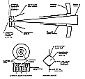
Figure II.C.4 Internal reference source assembly showing radiation path
from source to focal plane and details of thermal source design larger largest |
An assembly mounted behind the secondary mirror contained ten thermal
calibration sources, hereafter called "internal reference sources",
several of which were used to provide stable pulses of infrared radiation
for use as a reference during the mission and for ground testing prior
to launch. Figure II.C.4 shows the location of
the internal reference source assembly, the way in which a source illuminates
the focal plane through a small hole in the center of the secondary mirror,
and a cutaway view of an individual thermal source. The thermal source
consisted of a 1 mm square diamond substrate coated with nichrome film
and suspended by 0.051 mm diameter brass wires. During the mission an applied
voltage ohmically heated the substrate to ~200 K in 13/16 sec. Two optical
sources were included in the calibration assembly and used for ground testing
of the star sensors.

|
|
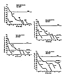
Figure II.C.5 Calculated out-of-field rejection performance of telescope
system compared to the total flux photometric reference, or TFPR
(Section VI.B), for 12, 25, 60 and
100 µm bands. The sunshade temperature was taken to be
95 K; the Earth was assumed to radiate as a 280 K blackbody; the moon,
Sun and Jupiter were taken as 370, 50O0 and 133 K black-bodies with
angular diameters of 31, 31, and 0.75', respectively. larger largest |
Out-of-field radiation was absorbed by aluminum baffle structures
which were coated with Martin Optical Black.
Figure II.C.5
shows the calculated out-of-field performance in the four wavelength
bands. The survey strategy (Section III.C)
limited the angle between the boresight and the Moon, Earth, Sun and Jupiter
to greater than 24°, 88°, 60° and 5°, respectively.
At these angles the out-of-field radiation from these sources is thought
to be negligible (see, however, Section III.B.5
and IV.C for a discussion of lunar
"glints").
Further discussion of the out-of-field performance is included in
Harned, Breault, and Melugin (1980).
Table of Contents | Index | Previous Section | Next Section