|
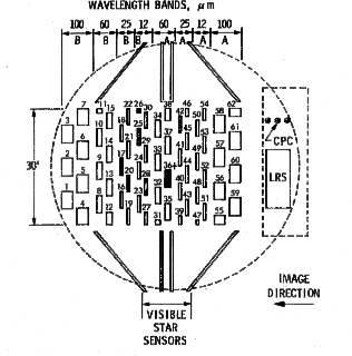
IRAS was a spacecraft with a telescope mounted in a liquid helium cooled cryostat. The telescope was a f/9.6 Ritchey-Chretien design with a 5.5 m focal length and a 0.57 m aperture. The mirrors were made of beryllium and cooled to approximately 4 K. The focal plane assembly contained the survey detectors, visible star sensors for position reconstruction, a Low Resolution Spectrometer (LRS) and a Chopped Photometric Channel (CPC). The focal plane assembly was located at the Cassegrain focus of the telescope and was cooled to about 3 K. IRAS Focal Plane
| |||||||||||||||||||||||||||||||||||||||||||||||||||||||||||||||||||||||||||||||||
| Survey Array | |||||
| Center Wavelength |
# working detectors |
FOV (arcmin) |
Bandpass (µm) |
Detector Material |
Average 10-sigma Sensitivity (Jy) |
| 12 | 16 | .75 x 4.5 | 8.5 - 15 | Si:As | 0.7 |
| 25 | 13 | .75 x 4.6 | 19 - 30 | Si:Sb | 0.65 |
| 60 | 15 | 1.5 x 4.7 | 40 - 80 | Ge:Ga | 0.85 |
| 100 | 13 | 3.0 x 5.0 | 83 - 120 | Ge:Ga | 3.0 |
| CPC | |||||
| Center Wavelength |
# working detectors |
FOV (arcmin) |
Bandpass (µm) |
Detector Material |
Average 10-sigma Sensitivity (Jy) |
| 50 | 1 | 1.2 | 41 - 63 | Ge:Ga | 7.0 |
| 100 | 1 | 1.2 | 84 - 114 | Ge:Ga | 7.0 |
| LRS | |||
| Slit width (arcmin) |
Wavelength Range (µm) |
Detector Material |
Resolving Power |
| 5.0 | 8 - 13 | Si:Ga | 14-35 |
| 7.5 | 11 - 23 | Si:As | 14-35 |
Survey Strategy
IRAS was launched in January of 1983 into a sun-synchronous near-polar (99 degree) orbit, which precessed by about a degree each day. The celestial sphere was divided into "lunes" bounded by ecliptic meridians 30 degrees apart. The survey covered the sky by "painting" each lune in overlapping strips as the satellite scanned through the lune during each orbit. Most (96%) of the sky was covered by at least two hours-confirming scans (HCONs) and 2/3 of the sky was covered by a third (which used a slightly different observing strategy). Some sources, near the ecliptic poles, had more than three hours-confirmed coverages.
One HCON was separated from the next by up to several months. Thus the data combined into a single image from the survey may have been taken over a period of many months, and are subject to variations in the actual observed foreground due to the changing geometry with which the zodiacal light was observed and to variations in detector response.
![]()
| <-- Previous Section | Next Section --> | |
| (Introduction to IRAS) | (Characteristics of IRAS Data) |


